
PIC 16F877A development board
This content will be shared across all product pages.
Description:
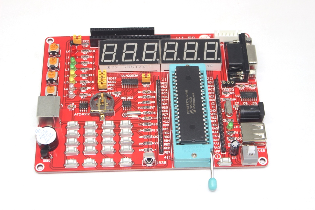
The PIC 16F877A Development Board is a versatile platform designed for prototyping and developing applications based on the PIC16F877A microcontroller. This development board provides an integrated environment for programming, testing, and interfacing with peripherals, making it ideal for educational purposes, hobbyist projects, and professional development.
Key Features:
- Based on the PIC16F877A microcontroller
- Onboard crystal oscillator for clock generation
- Reset circuitry with push-button reset
- Power supply options (typically via USB or external power adapter)
- Headers and connectors for easy access to I/O pins and peripherals
- Onboard LEDs for visual feedback
- UART, SPI, I2C interfaces for communication
- Expansion headers for adding additional modules and sensors
- Microcontroller: PIC16F877A
- Clock Frequency: Typically 20 MHz (crystal oscillator)
- Power Supply: Typically 5V DC
- Communication Interfaces: UART, SPI, I2C
- Onboard Components: LEDs, push buttons, reset circuit
- Expansion Headers: GPIO, analog inputs, PWM outputs
- Dimensions: Varies by board design
- Weight: Lightweight for portability
- Educational projects and labs
- Embedded system prototyping
- Sensor interfacing and data acquisition
- IoT (Internet of Things) applications
- Automation and control systems
Technical Specifications:
- Logic Family: CMOS
- Number of Channels: 3
- Switch Configuration: Single-Pole Double-Throw (SPDT)
- Supply Voltage Range: 3V to 15V
- “ON” Resistance (R_ON): 125Ω typical at V_DD = 10V
- “OFF” Leakage Current (I_OFF): ±100pA typical at V_DD = 10V
- Control Input Voltage (V_IH): 0.7 V_DD min, 0.3 V_DD max
- Maximum Operating Frequency: 40 MHz at V_DD = 10V
Applications:
- Signal routing and switching
- Analog and digital multiplexing
- Audio and video signal processing
- Data acquisition systems
- Test equipment