In today’s world, automation and smart security solutions are becoming increasingly essential for homes, offices, and industries. One effective way to enhance security is by using a motion-triggered camera system that automatically captures images or records videos whenever movement is detected. This project utilizes an ESP32-CAM module paired with a PIR (Passive Infrared) motion sensor to detect movement and trigger the camera, making it an ideal solution for surveillance applications. The ESP32-CAM is chosen over Arduino because of its built-in camera support, Wi-Fi connectivity, and ability to process images efficiently. By integrating the PIR sensor with the ESP32-CAM, the system can detect human presence and capture real-time footage, making it suitable for home security, wildlife monitoring, or even remote surveillance.
Components Required
- ESP32-CAM (Microcontroller with camera module)
- PIR Motion Sensor (Detects movement based on infrared radiation)
- FTDI Programmer (For programming the ESP32-CAM)
- MicroSD Card (Optional, for local image/video storage)
- Jumper Wires
- 5V Power Supply or Battery
Circuit Diagram
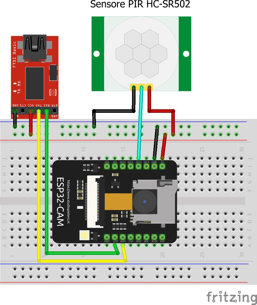
Component Connections
Connecting the PIR Sensor to ESP32-CAM
The PIR sensor detects motion by sensing changes in infrared radiation. When movement is detected, the sensor outputs a HIGH signal, which can be read by the ESP32-CAM.
Wiring the PIR Sensor to ESP32-CAM:
- VCC (Power Input) → Connect to 5V on ESP32-CAM
- GND (Ground) → Connect to GND on ESP32-CAM
- OUT (Signal Output) → Connect to GPIO13 on ESP32-CAM
Why Use a PIR Sensor?
The PIR sensor efficiently detects motion with minimal power consumption, making it suitable for battery-powered security systems.
Connecting the ESP32-CAM
Unlike Arduino boards, the ESP32-CAM requires an FTDI programmer for flashing the code. The connection is as follows:
- FTDI VCC → Connect to 5V on ESP32-CAM
- FTDI GND → Connect to GND on ESP32-CAM
- FTDI TX → Connect to U0R (RX) on ESP32-CAM
- FTDI RX → Connect to U0T (TX) on ESP32-CAM
- GPIO0 → Connect to GND (Only for programming mode)
Why Choose ESP32-CAM Over Arduino?
The ESP32-CAM is preferred because:
- Built-in Camera Support: It has a dedicated OV2640 camera module, unlike Arduino, which would require an external camera shield.
- Wi-Fi Connectivity: Allows remote access to captured images or videos, making it useful for real-time monitoring.
- Higher Processing Power: Capable of handling image processing tasks efficiently.
Powering the System
The ESP32-CAM operates on 3.3V or 5V, but for stable performance, a 5V power supply is recommended. Avoid using the 3.3V output from an FTDI adapter, as it may not provide enough current.
Installing the Components
Mounting the PIR Sensor
- Position the PIR sensor in a location with a clear field of view.
- Secure it to the enclosure to avoid unwanted movements that may trigger false alerts.
Setting Up the Camera Module
- Ensure the ESP32-CAM’s camera ribbon cable is properly inserted.
- Position the camera to cover the desired surveillance area.
Uploading the Code to ESP32-CAM
- Open Arduino IDE and install the ESP32 board package.
- Select the ESP32 Wrover Module board.
- Paste the provided Arduino code.
- Connect the FTDI programmer to the ESP32-CAM.
- Hold the GPIO0 pin LOW while uploading the code.
- Once uploaded, restart the ESP32-CAM by disconnecting and reconnecting power.
Code
|
Code Explanation
Including Libraries
#include "esp_camera.h" #include "Arduino.h" |
- esp_camera.h: This library helps the ESP32-CAM to control the camera module.
- Arduino.h: The core Arduino functions like pinMode() and digitalRead() are included here.
Defining Camera Pins
|
These #define lines assign the GPIO pins of the ESP32-CAM board that are connected to the camera module.
What are GPIO Pins?
GPIO means General Purpose Input/Output pins. They are used to connect sensors, cameras, or LEDs to the board.
PIR Sensor Pin
#define PIR_SENSOR_PIN 13 |
The PIR sensor is connected to GPIO Pin 13.
Setup Function (Initial Setup)
|
- Serial.begin(115200): This allows the board to print messages to your computer to check what's happening.
- pinMode(PIR_SENSOR_PIN, INPUT): The PIR sensor detects motion, so it is set as an input device.
Camera Configuration
|
Important Parameters
Parameter | Purpose |
pixel_format | Defines the image format (JPEG) |
frame_size | Image resolution (UXGA or SVGA) |
jpeg_quality | Quality of the image (Lower number = Better quality) |
fb_count | Number of frames to store |
Checking External RAM (PSRAM)
|
Camera Initialization
|
This code starts the camera.
If the camera doesn't start, it will print an error message.
Loop Function (Main Program)
|
In this section:
- The PIR sensor detects motion.
- If motion is detected, the camera captures an image.
Capturing Image
|
- The camera takes the picture and saves it temporarily in memory (frame buffer).
- If the camera fails, it will print "Camera capture failed".
Free the Memory
esp_camera_fb_return(fb); |
This releases the camera memory to avoid crashes.
Delay to Prevent Continuous Triggering
delay(5000); |
The system waits 5 seconds before detecting motion again.
Observing Functionality
- Normal Mode: The ESP32-CAM remains idle.
- Motion Detected: The camera captures an image.
- Captured Image: Stored in RAM or an SD card, or sent via Wi-Fi.
Common Problems and Solutions
- ESP32-CAM Not Responding?
- Ensure GPIO0 is LOW while uploading code.
- Use a stable 5V power source.
- PIR Sensor False Triggers?
- Reduce sensitivity using PIR adjustment knobs.
Conclusion
This motion-triggered camera system efficiently detects movement and captures images, making it an excellent security solution. The ESP32-CAM’s built-in camera, Wi-Fi capabilities, and ability to interface with sensors make it the ideal choice for real-time surveillance applications.