
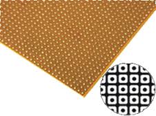
Vero Board small size dotted
A small size dotted Vero board, also known as a stripboard or prototyping board, is a type of circuit board that is used for prototyping and building electronic circuits. It features a grid of holes with copper pads that allow components to be easily soldered onto the board. The dotted pattern provides flexibility in layout, making it ideal for custom circuit designs and small electronic projects.
Key Features:
- Dotted pattern for versatile circuit layout
- High-quality FR4 material for durability
- Copper pads for easy soldering
- Small size for compact projects
- Compatible with through-hole components
- Suitable for prototyping and custom circuit building
- Material: FR4 (fiberglass epoxy laminate)
- Size: Typically around 70mm x 90mm (varies by manufacturer)
- Hole Pitch: 2.54mm (standard 0.1 inch grid)
- Hole Diameter: 1.0mm (suitable for most through-hole components)
- Thickness: 1.6mm
- Copper Thickness: 35µm (1oz/ft²)
- Pattern: Dotted (individual copper pads)
- Number of Holes: Varies by board size (e.g., 25x35 grid for 70mm x 90mm board)
- Prototyping electronic circuits
- Custom circuit design
- DIY electronics projects
- Educational and learning purposes
- Small-scale production of custom circuits
- Design the Circuit:
- Plan the layout of your components and connections on the Vero board.
- Place the Components:
- Insert the components into the holes according to your circuit design.
- Solder the Components:
- Solder the component leads to the copper pads on the reverse side of the board.
- Create Connections:
- Use solder bridges or wire links to create electrical connections between the copper pads as needed.
- Test the Circuit:
- Verify the circuit functionality and make any necessary adjustments or corrections.
- Ensure proper soldering techniques to avoid short circuits or poor connections.
- Handle the board carefully to avoid damaging the copper pads or FR4 material.
- Verify the component placement and connections before powering the circuit.