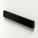
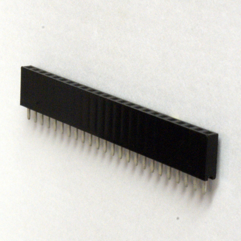
2.54mm Female SIL header
This content will be shared across all product pages.
The 2.54mm Female SIL (Single Inline) header is a type of connector used to interface with electronic circuits. It features a row of female sockets that match a 2.54mm (0.1 inch) pin spacing, making it suitable for use with standard pin headers. This component is commonly used in circuit boards for connecting various electronic components, such as ICs and modules, providing a reliable connection in a compact and space-efficient form.
Key Features:
- 2.54mm (0.1 inch) pin spacing
- Female connectors for interfacing with male pin headers
- Single row configuration
- Suitable for PCB mounting
- Reliable and durable connection
- Pitch (Pin Spacing): 2.54mm (0.1 inch)
- Configuration: Single row
- Number of Pins: Varies (e.g., 2, 4, 8, 16 pins)
- Contact Material: Typically brass or copper alloy
- Contact Plating: Gold or tin plating (varies by manufacturer)
- Body Material: Plastic (often nylon or PBT)
- Operating Temperature Range: -20°C to +85°C (typical)
- Voltage Rating: Up to 250V (depending on specific header)
- Current Rating: Typically 1A to 2A per pin (depending on specific header)
- PCB Interfacing: Used for connecting components to a printed circuit board (PCB).
- Prototyping: Commonly used in breadboards and prototyping boards for circuit development.
- Module Connections: Suitable for interfacing with modules and expansion boards.
- Consumer Electronics: Applied in various electronic devices and systems.
- Insert the female SIL header into the designated holes on the PCB or prototyping board.
- Solder the header pins to secure it in place.
- Connect the male pin headers or components to the female sockets.
- Ensure proper alignment and insertion to avoid damaging the header or PCB.
- Verify that the pin spacing matches the male headers or components you are connecting.
- Avoid applying excessive force during insertion or removal to prevent damage.
Technical Specifications:
- Logic Family: CMOS
- Number of Channels: 3
- Switch Configuration: Single-Pole Double-Throw (SPDT)
- Supply Voltage Range: 3V to 15V
- “ON” Resistance (R_ON): 125Ω typical at V_DD = 10V
- “OFF” Leakage Current (I_OFF): ±100pA typical at V_DD = 10V
- Control Input Voltage (V_IH): 0.7 V_DD min, 0.3 V_DD max
- Maximum Operating Frequency: 40 MHz at V_DD = 10V
Applications:
- Signal routing and switching
- Analog and digital multiplexing
- Audio and video signal processing
- Data acquisition systems
- Test equipment