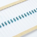
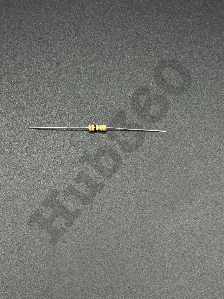
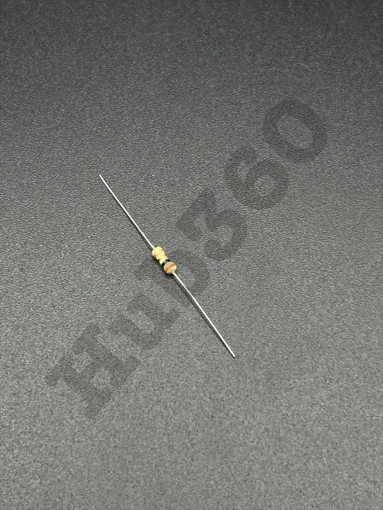
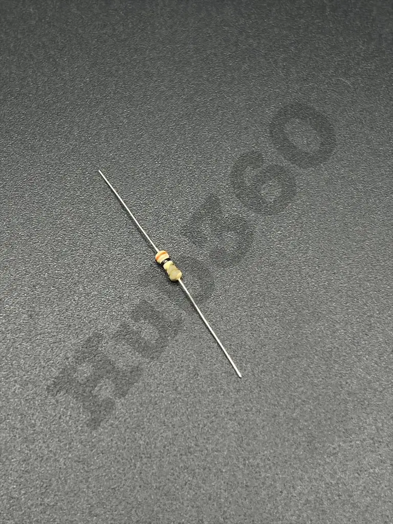
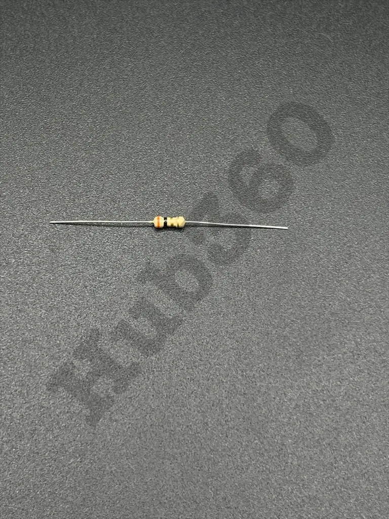
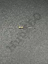
3Ω 1/4W resistor
A 3Ω (ohm) 1/4 watt resistor is a fixed resistor with a resistance value of 3 ohms and a power dissipation rating of 0.25 watts (1/4W). It is used in electronic circuits to limit current, divide voltages, and perform other functions requiring precise resistance.
Key Features:
- Resistance: 3Ω
- Power Rating: 1/4W (0.25 watts)
- Tolerance: ±5% (commonly), though other tolerances such as ±1% are available
- Temperature Coefficient: Typically ±100ppm/°C or ±200ppm/°C for general-purpose resistors
- Resistance: 3Ω
- Power Rating: 1/4W (0.25 watts)
- Tolerance: ±5% (J), ±1% (F), depending on the type
- Temperature Coefficient: ±100ppm/°C or ±200ppm/°C
- Operating Temperature Range: -55°C to +155°C
- Body Size: Standard through-hole resistors typically come in axial packages (e.g., 1/4W size)
- Material: Carbon film, metal film, or metal oxide, depending on the specific resistor type
- Current Limiting: Used to limit the amount of current flowing through a circuit.
- Voltage Division: Employed in voltage divider circuits to create specific voltage levels.
- Biasing: Used in transistor biasing circuits to set operating points.
- Signal Conditioning: Used in various signal processing applications to adjust signal levels.
- LED Protection: Used to limit current through LEDs to prevent damage.
- Timing Circuits: Paired with capacitors in RC timing circuits.
- Determine Placement: Identify the location on the circuit board where the resistor is needed.
- Insert Resistor: For through-hole resistors, insert the leads into the appropriate holes on the PCB.
- Soldering: Solder the leads to the PCB pads and trim any excess lead length.
- Verify Installation: Ensure the resistor is securely soldered and check for proper resistance with a multimeter if needed.
- Power Dissipation: Do not exceed the power rating (0.25W) to prevent overheating and potential damage.
- Voltage Rating: Ensure the voltage across the resistor does not exceed its voltage rating.
- Handling: Handle with care to avoid physical damage to the resistor body and leads.