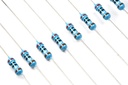
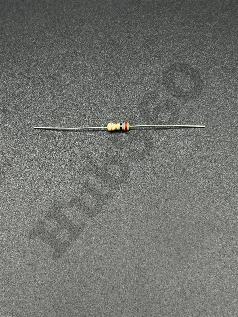
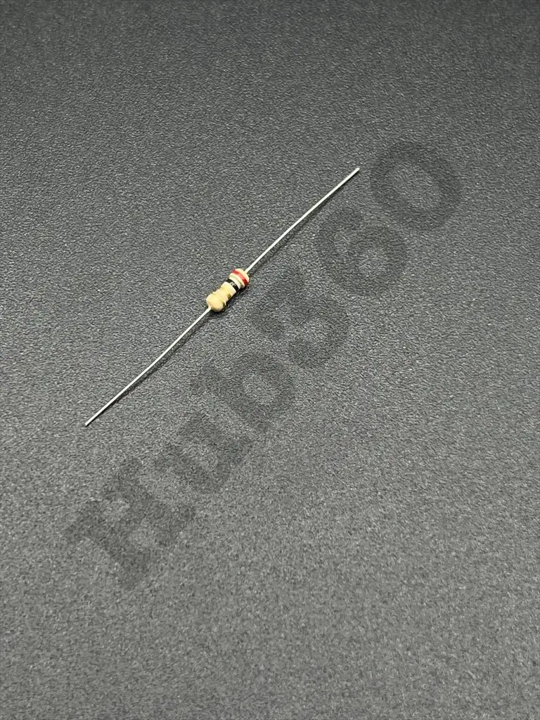
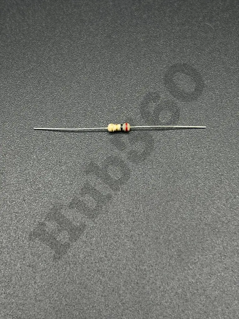
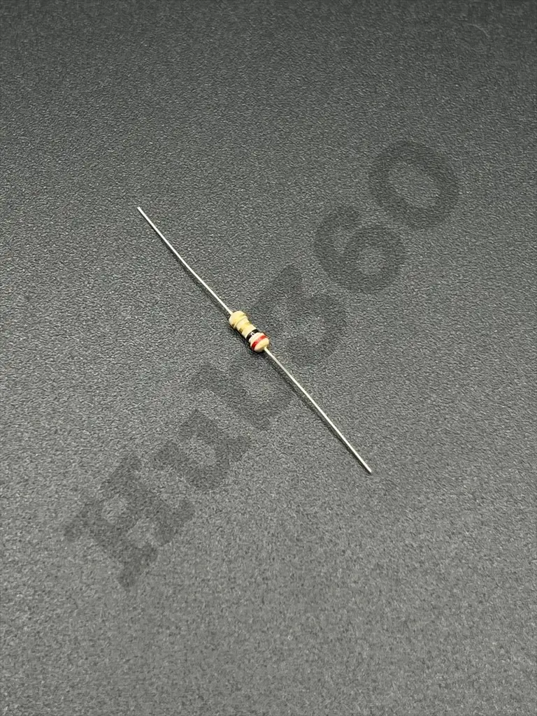
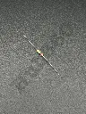
2Ω 1/4W resistor
The 2Ω 1/4W resistor is a fixed-value resistor with a resistance of 2 ohms, capable of dissipating up to 1/4 watt of power. It is commonly used in various electronic circuits for current limiting, biasing, and other general applications where a low resistance value is required.
Key Features:
- Resistance: 2 ohms
- Power Rating: 1/4 watt (0.25W)
- Tolerance: Typically ±5% (can vary by manufacturer)
- Type: Carbon film or metal film
- Resistance: 2Ω
- Power Rating: 1/4W (0.25W)
- Tolerance: ±5% (standard), other tolerances available
- Temperature Coefficient: Typically ±100ppm/°C to ±300ppm/°C (varies by type)
- Operating Temperature Range: -55°C to +155°C
- Body Color: Commonly beige or blue (depends on manufacturer)
- Lead Type: Axial leads for through-hole mounting
- Dimensions: Length and diameter can vary, but typically around 6.3mm x 2.3mm
- Current Limiting: Used to limit the current flowing through a circuit.
- Voltage Division: Used in voltage divider circuits to obtain a desired voltage.
- Biasing: Provides biasing in amplifier and transistor circuits.
- Pull-up/Pull-down: Acts as pull-up or pull-down resistors in digital circuits.
- Timing Circuits: Used in conjunction with capacitors for timing applications.
- Identify the Correct Resistance Value: Ensure that 2Ω is the required resistance for your circuit.
- Check the Power Rating: Verify that 1/4W is sufficient for your application to avoid overheating.
- Position on PCB: Place the resistor in the appropriate location on the printed circuit board (PCB).
- Soldering: Solder the axial leads of the resistor to the PCB, ensuring good mechanical and electrical connections.
- Verification: Test the circuit to ensure proper functionality and that the resistor is operating within its specified limits.
- Power Dissipation: Do not exceed the 1/4 watt power rating to prevent damage or failure.
- Temperature Range: Operate within the specified temperature range to ensure reliable performance.
- Handling: Handle with care to avoid mechanical damage to the resistor body and leads..