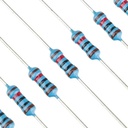

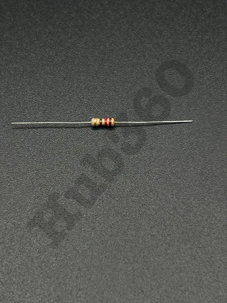
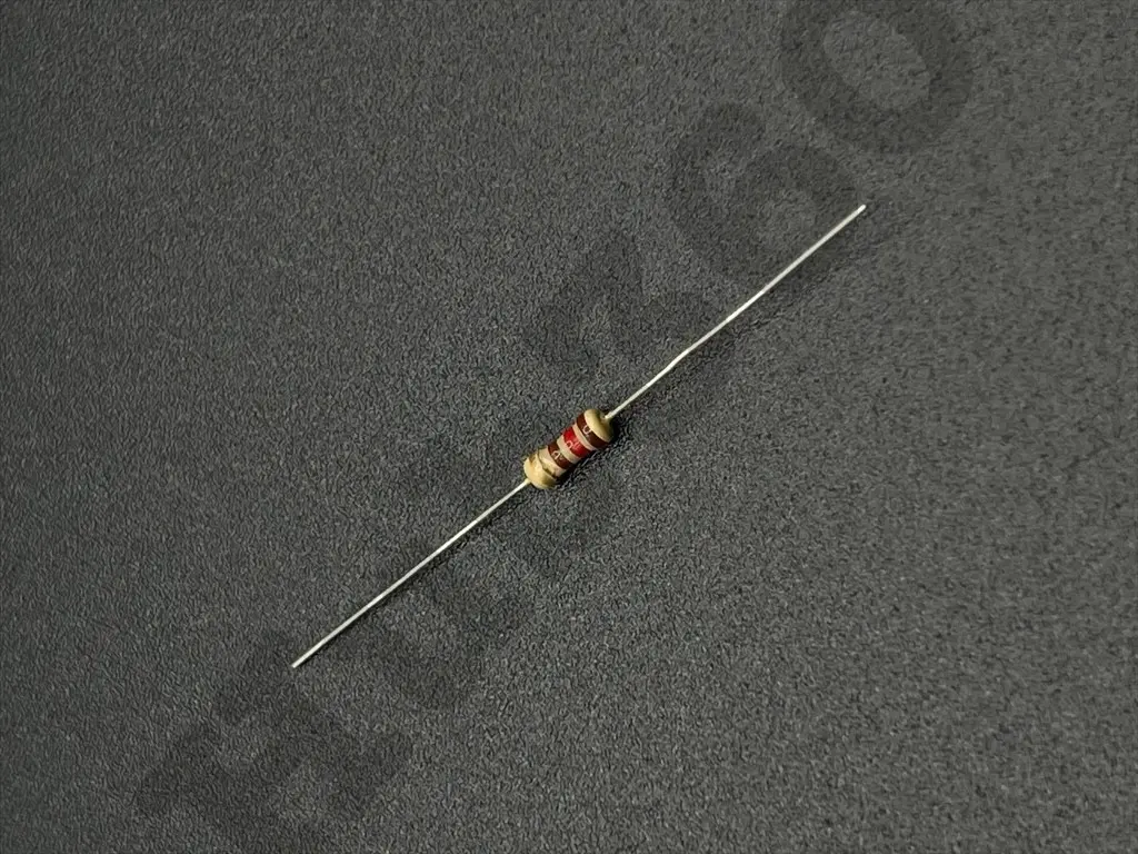
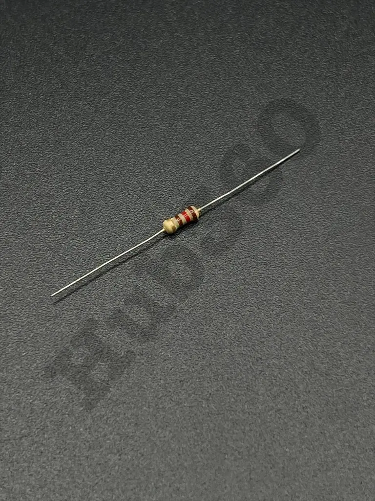
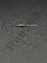
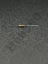
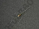
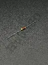
120Ω 1/4W resistor
The 120Ω 1/4W resistor is a fixed-value resistor with a resistance of 120 ohms (Ω) and a power rating of 1/4 watt (W). Resistors are essential components in electronic circuits, used to limit current flow, divide voltages, and perform other critical functions.
Key Features:
- Resistance: 120Ω
- Power Rating: 1/4 watt (0.25W)
- Tolerance: Typically ±5% (J) or ±1% (F), depending on the specific resistor
- Temperature Coefficient: Varies by type, commonly ±200ppm/°C for general-purpose resistors
- Resistance: 120Ω
- Power Rating: 1/4W (0.25W)
- Tolerance: ±5% (standard) or ±1% (precision)
- Maximum Working Voltage: Typically up to 250V (check specific resistor marking)
- Temperature Coefficient: Typically ±200ppm/°C
- Operating Temperature Range: -55°C to +155°C
- Body Size: Generally follows standard sizes for through-hole resistors, such as 2.4mm x 6.3mm
- Current Limiting: Used to limit the current flow in a circuit.
- Voltage Division: Employed in voltage divider networks to obtain specific voltage levels.
- Biasing: Used in biasing active components like transistors and operational amplifiers.
- Pull-up/Pull-down: Used as pull-up or pull-down resistors in digital circuits.
- Signal Conditioning: Helps in shaping and conditioning analog and digital signals.
- Load Resistor: Used to simulate a load in testing and measurement applications.
- Identify the Correct Value: Ensure that 120Ω is the required resistance for your application.
- Check Power Rating: Verify that 1/4W is adequate for the power dissipation in your circuit.
- Position on PCB: Place the resistor in the appropriate location on the printed circuit board (PCB).
- Soldering: Solder the resistor leads to the PCB pads, ensuring good mechanical and electrical connections.
- Verification: Test the circuit to ensure proper functionality and that the resistor is operating within its specified limits.
- Power Rating: Do not exceed the rated power to avoid overheating and potential failure.
- Voltage Rating: Ensure the voltage across the resistor does not exceed its maximum working voltage.
- Handling: Handle with care to avoid damaging the resistor leads or body.