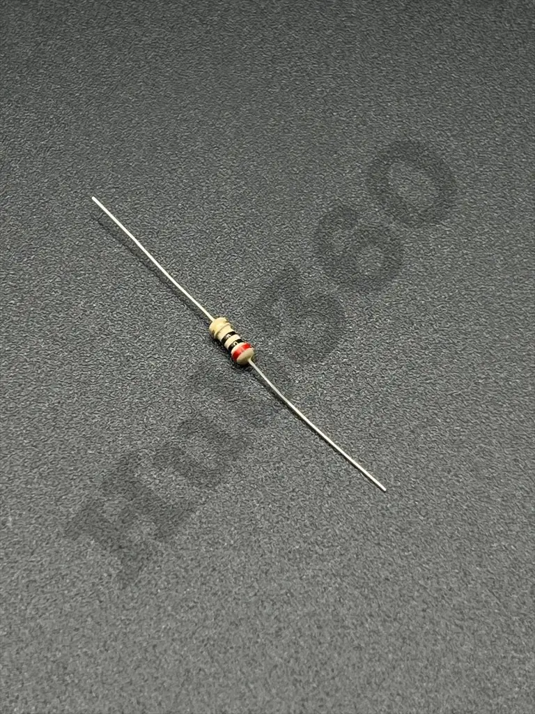
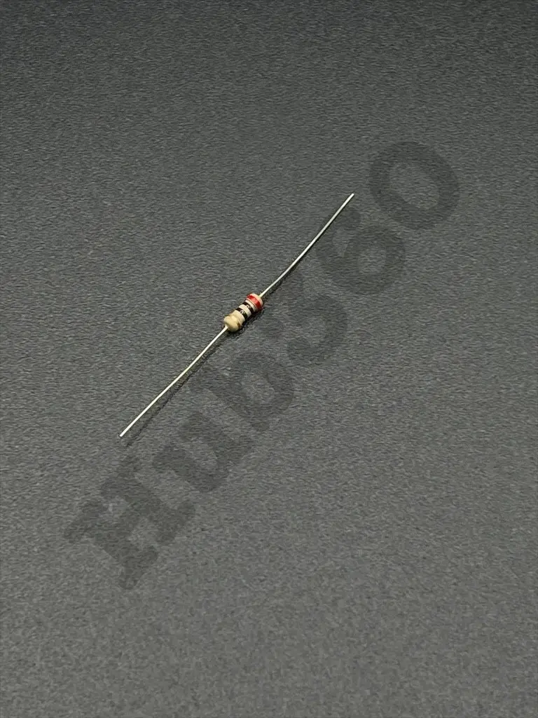
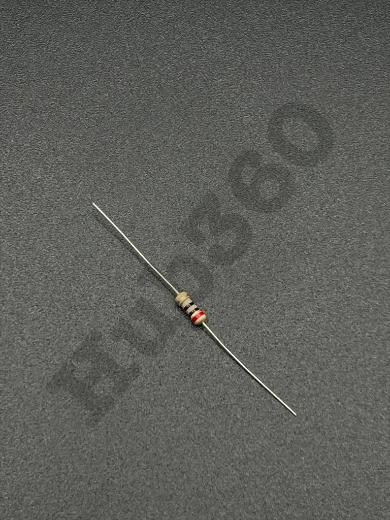
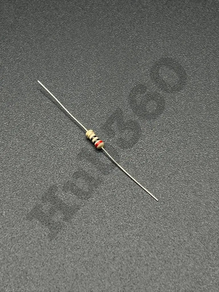
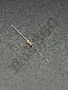
20Ω 1/4W resistor
The 20Ω 1/4W resistor is a common passive electronic component used to limit current, divide voltages, and provide biasing in electronic circuits. With a power rating of 1/4 watt (0.25W), it is suitable for low to moderate power applications. The resistor helps in controlling the flow of electrical current within a circuit to ensure proper operation and protection of sensitive components.
Key Features:
- Resistance of 20Ω
- Power rating of 1/4 watt (0.25W)
- Precision and stability in resistance value
- Standard tolerance of ±5% or ±1% (varies by manufacturer)
- Suitable for various electronic applications
- Resistance: 20Ω
- Power Rating: 1/4 watt (0.25W)
- Tolerance: ±5% or ±1% (varies by manufacturer)
- Temperature Coefficient: Varies by type (e.g., ±100ppm/°C)
- Body Size: Typically cylindrical (e.g., 3.2mm diameter x 6.5mm length for through-hole resistors)
- Mounting Type: Through-hole or surface-mount
- Material: Metal film, carbon film, or wirewound (varies by type)
- Current Limiting: Protects components by limiting the amount of current flowing through the circuit.
- Voltage Division: Used in voltage divider circuits to obtain a desired voltage.
- Biasing: Provides biasing for transistors and other semiconductor devices.
- Signal Conditioning: Helps in filtering and conditioning electronic signals.
- Load Resistors: Acts as a load in circuits for testing and calibration.
- Identify the resistor's resistance value and power rating suitable for your circuit.
- Choose the appropriate resistor type (e.g., through-hole or surface-mount) based on your PCB design.
- Insert the resistor into the designated location on the PCB.
- Solder the resistor leads or pads, ensuring secure and reliable connections.
- Verify circuit functionality to ensure correct operation with the installed resistor.
- Ensure the resistor's power rating is not exceeded to prevent overheating and damage.
- Verify the correct resistance value and tolerance to match circuit requirements.
- Handle with care to avoid physical damage, which may affect performance.