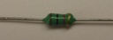
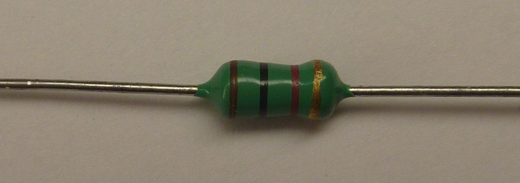
1mH inductor
This content will be shared across all product pages.
A 1mH inductor is a passive electronic component that stores energy in a magnetic field when electrical current flows through it. Inductors are widely used in power supply circuits, filtering applications, and in various electronic devices to manage current and voltage fluctuations.
Key Features:
- Inductance value of 1mH
- Low DC resistance for efficient performance
- High current handling capability
- Shielded or unshielded options available
- Compact and durable design
- Inductance: 1mH
- Tolerance: ±10% (typical)
- DC Resistance (DCR): Varies by model, typically around 0.5 to 2 ohms
- Rated Current: Typically around 0.1A to 1A (depending on specific inductor model)
- Self-Resonant Frequency: Typically in the range of 100kHz to 1MHz
- Operating Temperature Range: -40°C to +125°C
- Core Material: Ferrite or iron powder (depends on specific inductor model)
- Package Type: Radial leaded, axial leaded, or surface-mount (depends on specific inductor model)
- Dimensions: Varies by specific model, typically around 7mm x 7mm x 5mm (for surface-mount types)
- Power Supply Circuits: Used in DC-DC converters and power management circuits.
- Filtering: Helps in removing noise and ripple in power supply lines.
- RF Applications: Used in RF circuits for impedance matching and signal filtering.
- Chokes: Acts as a choke in various circuits to block AC while allowing DC to pass.
- Audio Equipment: Used in crossover networks for audio signal processing.
- General Purpose: Suitable for various electronic circuits requiring a 1mH inductance.
- Identify the correct placement for the inductor in your circuit based on the schematic.
- Ensure the inductor’s current rating matches the circuit’s requirements.
- Solder the inductor into place, ensuring secure connections to prevent signal loss.
- Test the circuit to verify the inductor is functioning as expected.
- Ensure the inductor's current rating is not exceeded to prevent overheating.
- Handle with care to avoid damaging the inductor or its leads.
- Verify the inductor's specifications match the requirements of your application.
Technical Specifications:
- Logic Family: CMOS
- Number of Channels: 3
- Switch Configuration: Single-Pole Double-Throw (SPDT)
- Supply Voltage Range: 3V to 15V
- “ON” Resistance (R_ON): 125Ω typical at V_DD = 10V
- “OFF” Leakage Current (I_OFF): ±100pA typical at V_DD = 10V
- Control Input Voltage (V_IH): 0.7 V_DD min, 0.3 V_DD max
- Maximum Operating Frequency: 40 MHz at V_DD = 10V
Applications:
- Signal routing and switching
- Analog and digital multiplexing
- Audio and video signal processing
- Data acquisition systems
- Test equipment